


Dumbleland Special #011 –
a technical analysis
Howard Alexander Dumble never built anything for a catalog. There was no mass production, no parts lists from the factory, and no sales department. Every amplifier that left his workshop was one-of-a-kind—and most disappeared behind closed doors, into private collections, or onto the unreachable stages of great musicians. Technically, not much is known… until now!
The Overdrive Special made the name legendary. But before it existed, Dumble built a series that is little more than a rumor even among connoisseurs: the Dumbleland Special. Depending on the source, there are between ten and twelve copies. All handmade, all from the late 1970s, all with a circuit design philosophy that Dumble later partly continued—and partly discarded.
Personal Note
The fact that an amplifier like this ends up on our workbench and we get to document it at our leisure—that’s not something to be taken for granted. For me personally, it’s simply unbelievable.
As far as we know, there is only one other circuit diagram for a Dumbleland Special: number 009, traced by hand. However Dumbleland Special #008 has already been listed on Reverb. Of course, there are no official documents. If you compare the two plans side by side, you’ll immediately see that they differ in several places. Presumably, Dumble himself developed the model; he reportedly customized the amplifier personally for each customer. Of course, we can never completely rule out the possibility of subsequent modifications to our specimen, but they seem rather unlikely in most places. Where there are doubts, this is noted in the plan.
What follows here is a bit of amplifier history. Deluxe Amp Archaeology.
Researched to the best of my knowledge and belief—enjoy reading it, Anselm.

Circuit Diagram


Iron You Can See and Hear

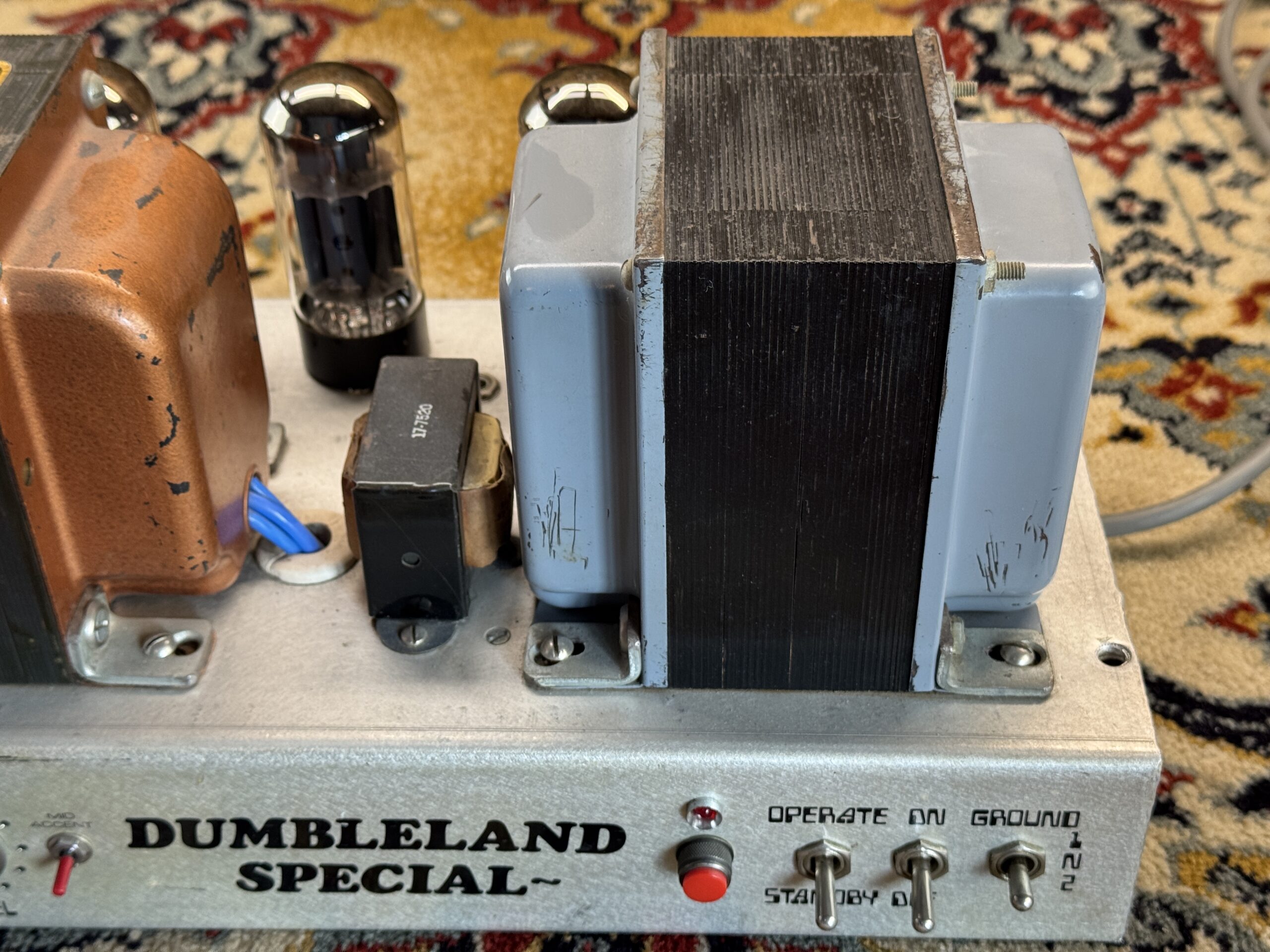
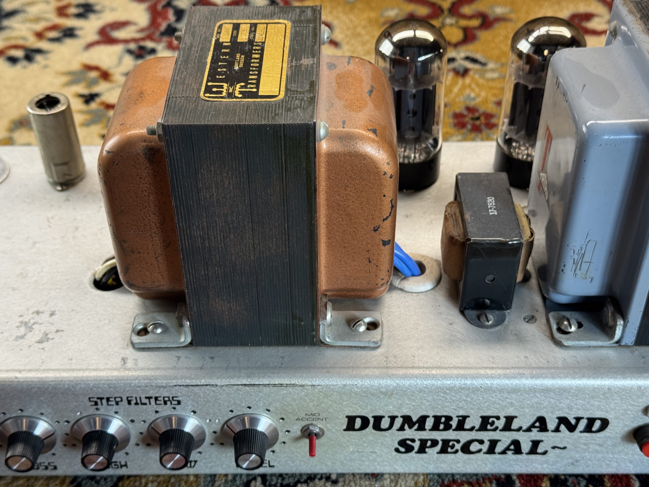
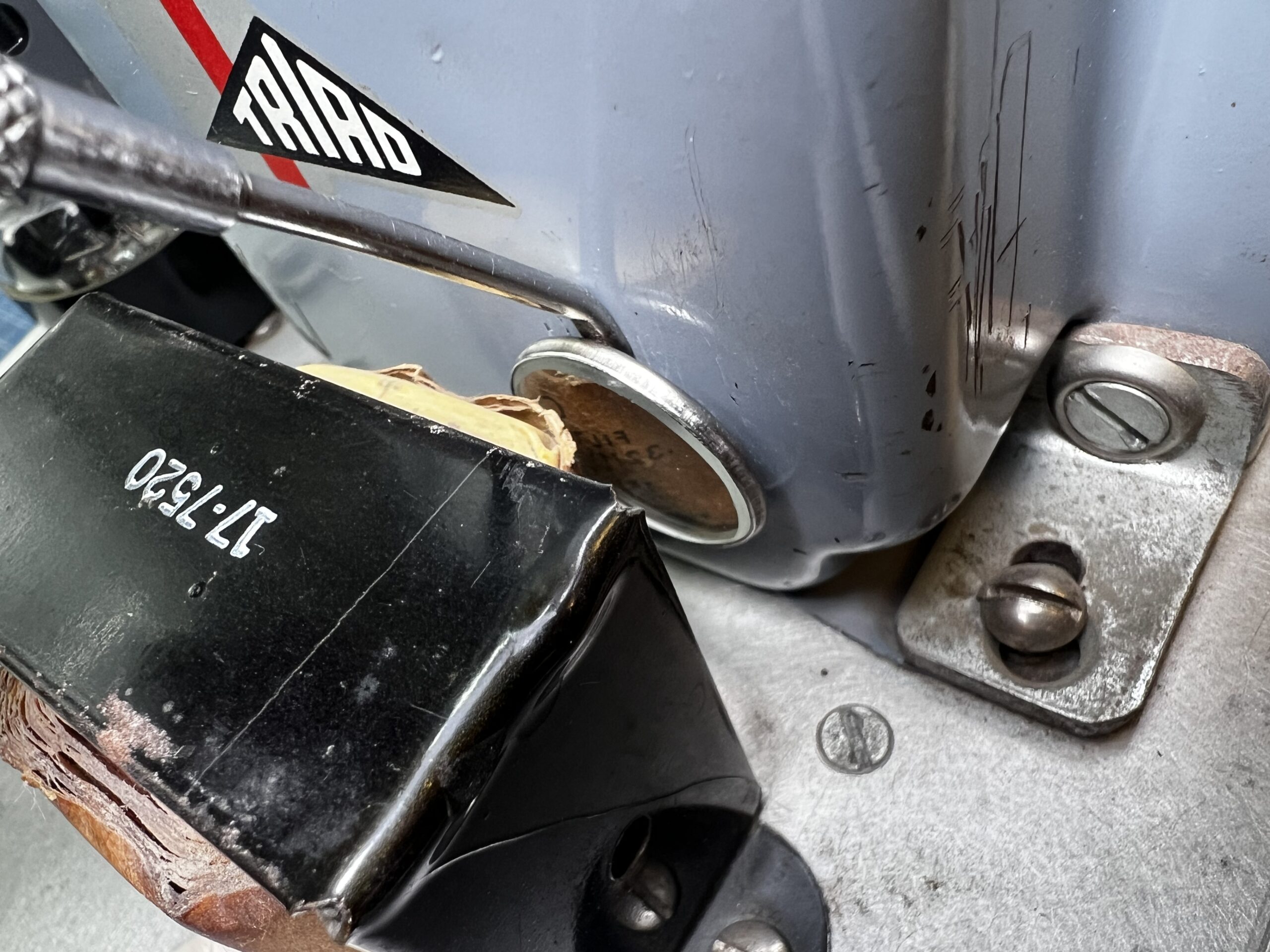
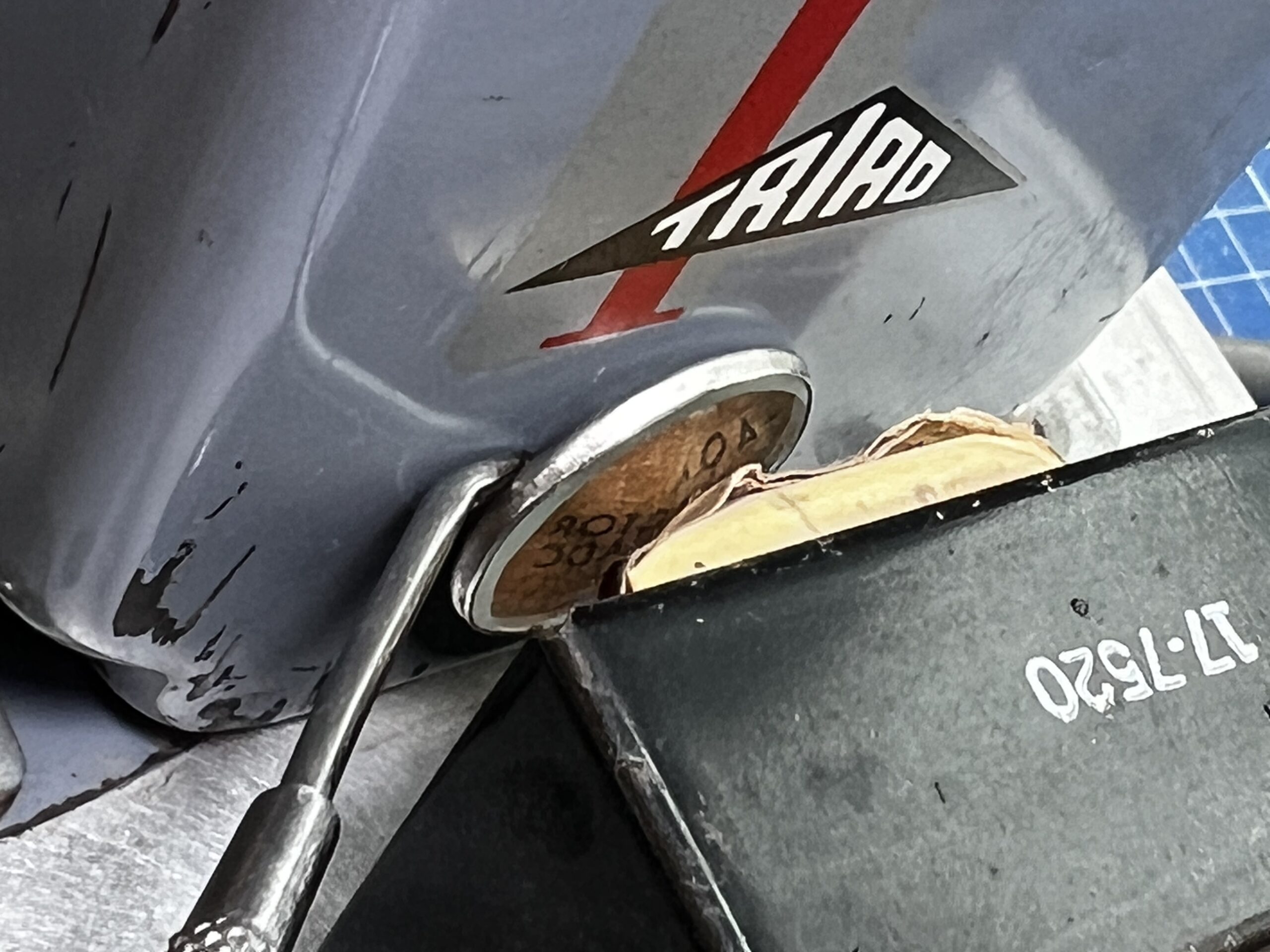
The first thing you notice: The transformers are huge. The power transformer is a Triad R-25A—a model you’d more likely expect to find in a hi-fi power amplifier. What’s interesting here is that the 5-V winding remains unused, while one of the two 6.3-V windings powers only the pilot light. Dumble deliberately chose an oversized transformer here and used only what he needed.
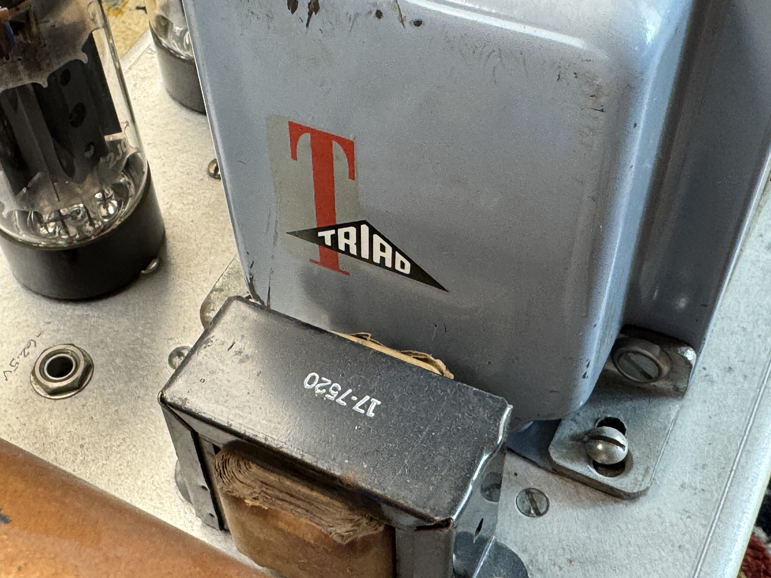
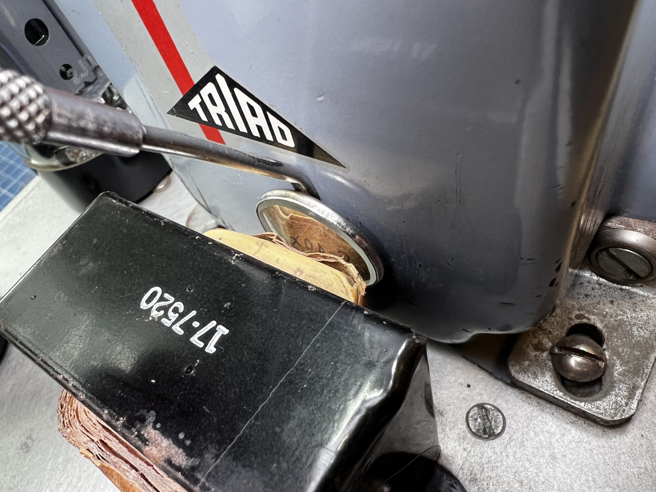
The output transformer is from Western Transformers in Portland, Oregon, and bears the customer number 29-1312—perhaps a custom order? The choke is a Triad C-40X.
Choke Input Filtering: Dumble Thinks Differently
One detail that immediately catches the eye when reading the schematic: The choke is located before the first anode tap. That’s choke-input filtering—a principle familiar from early Fender Pro models or the Orange 200. It provides a smoother, current-limited high voltage, resulting in natural sag behavior.
But Dumble wouldn’t be Dumble if he had just copied it. The resistance and inductance values differ significantly from those of Fender and Orange—they are set lower and more controlled. The result: Say yes, but without a sponge. Flexibility with control.
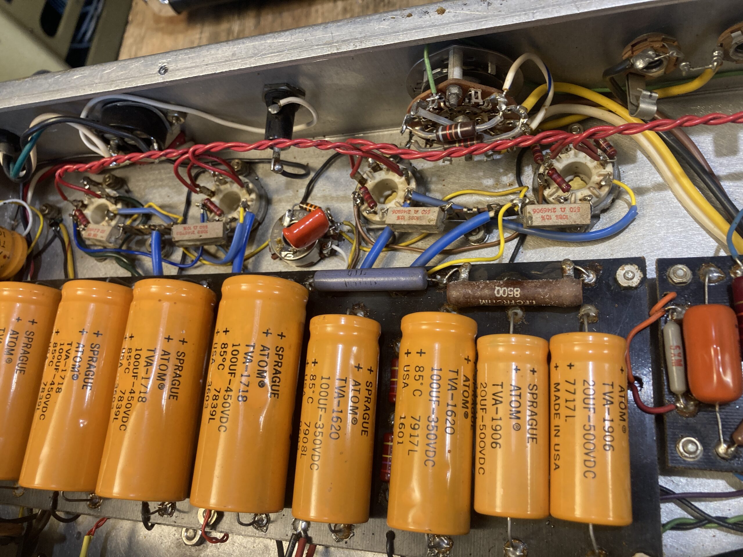
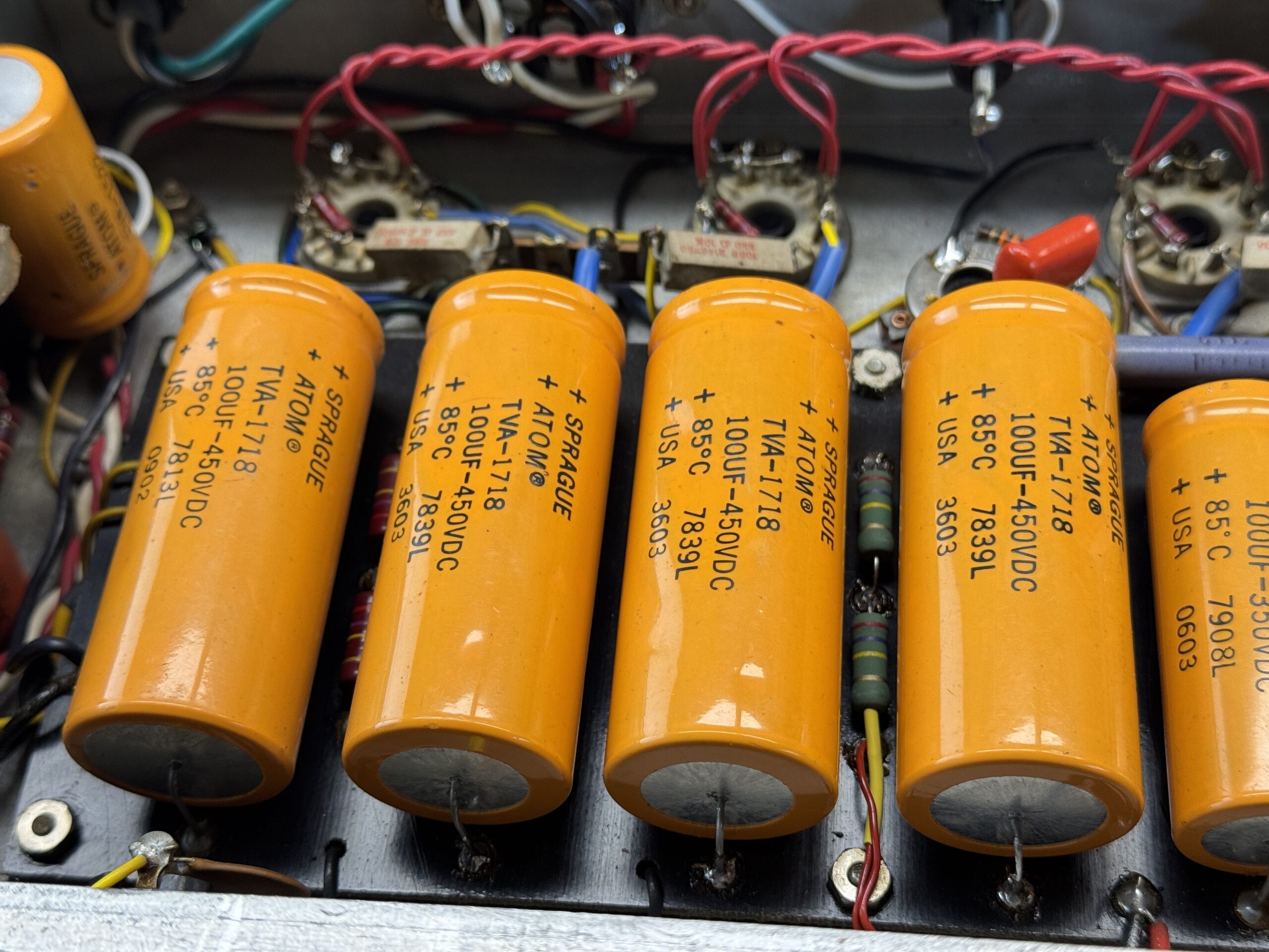
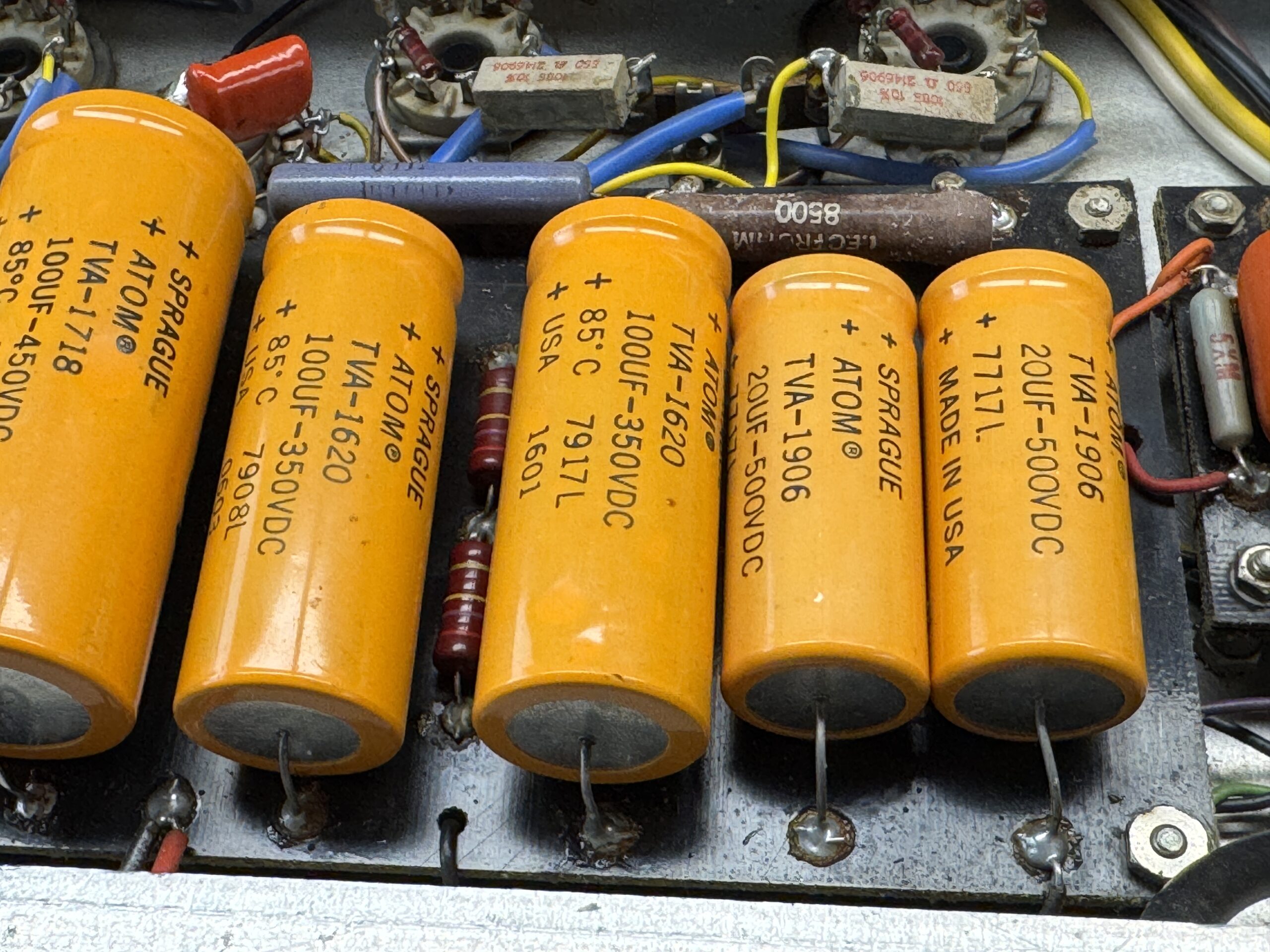
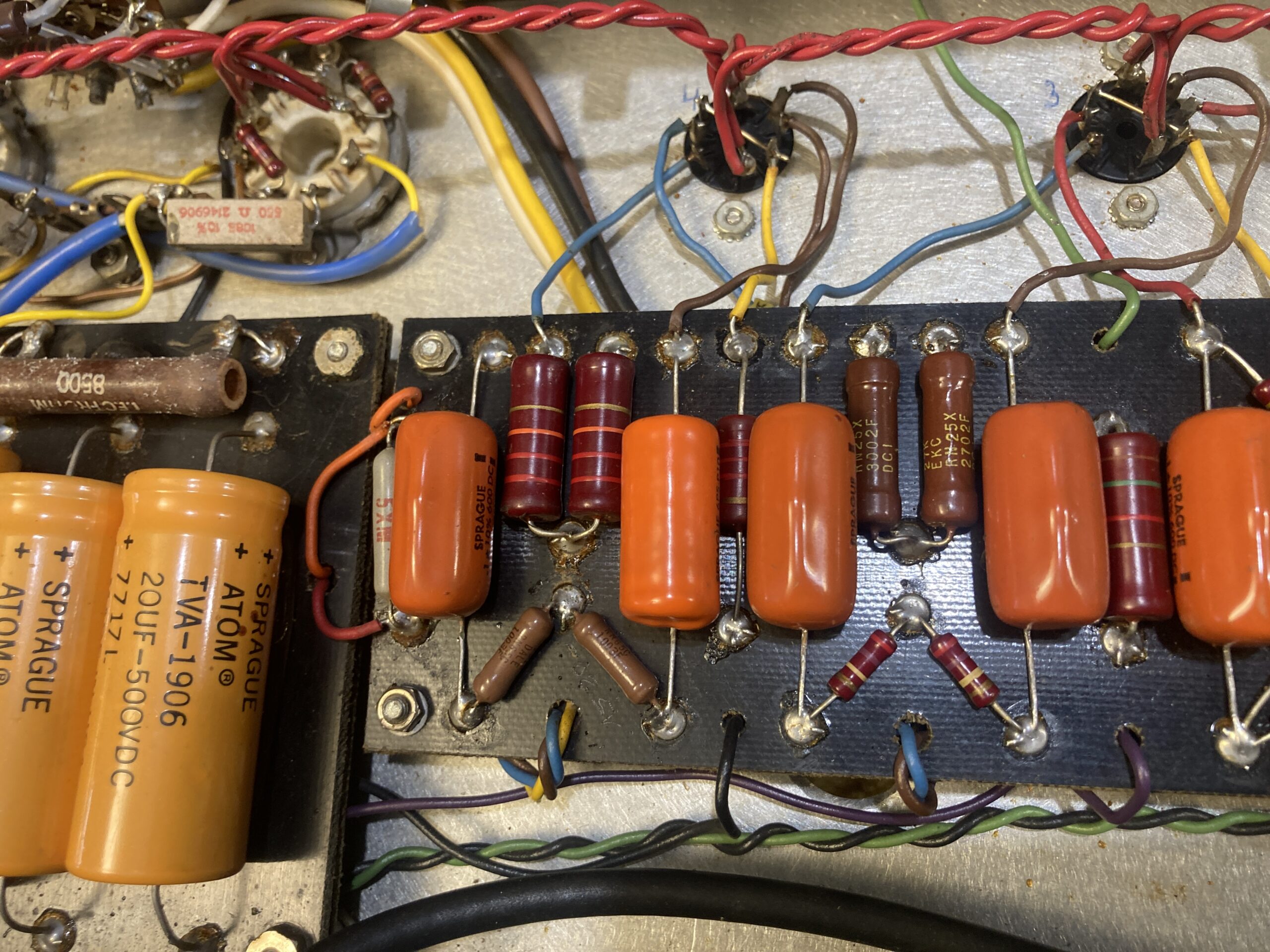
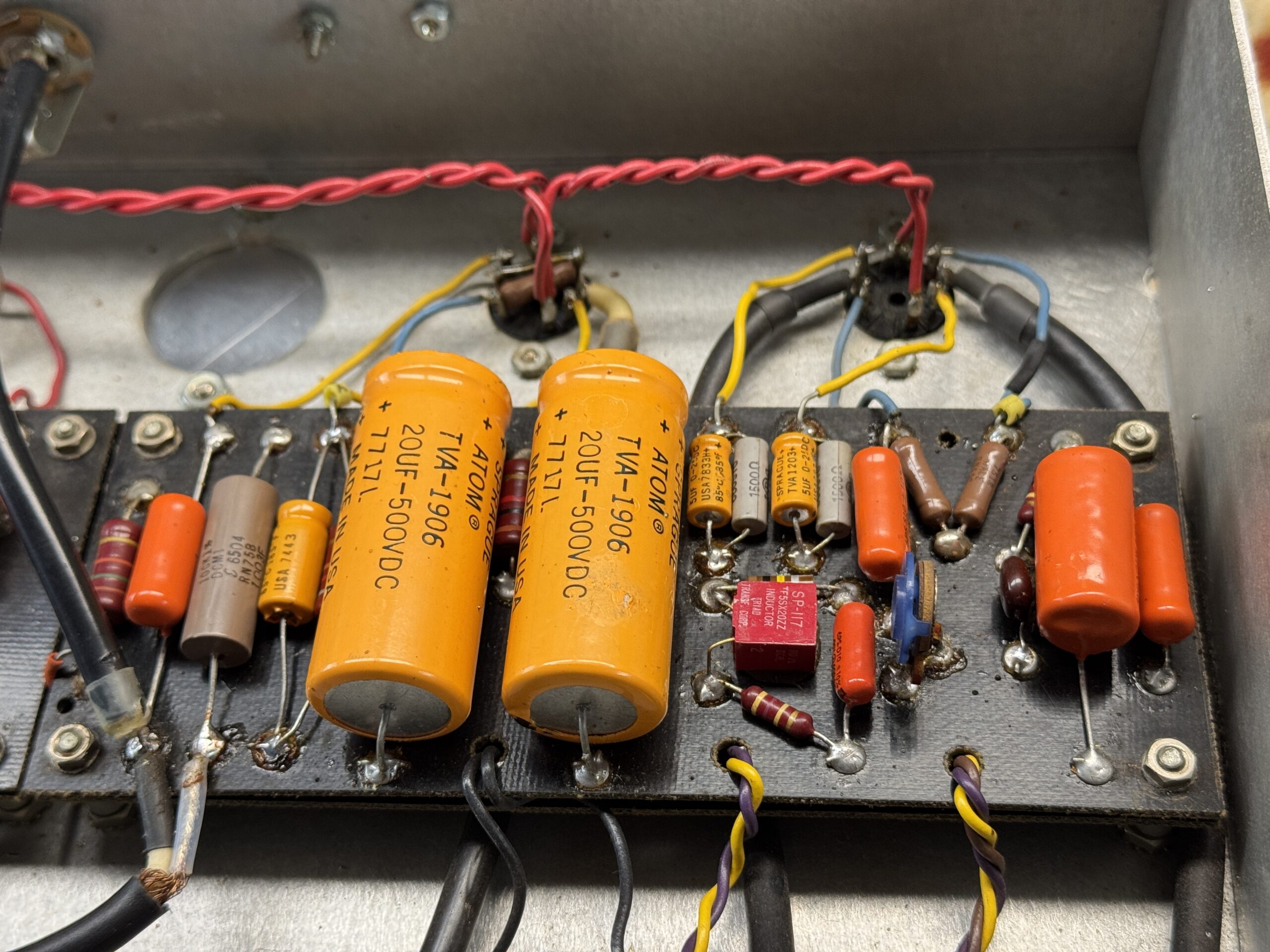
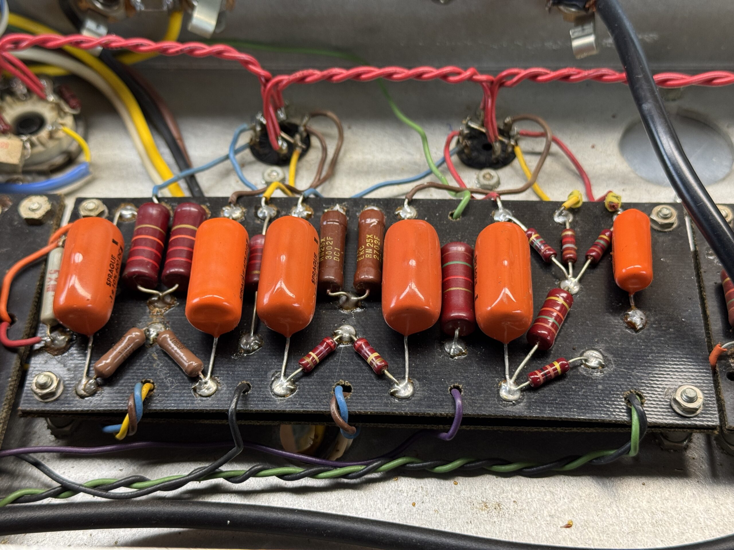
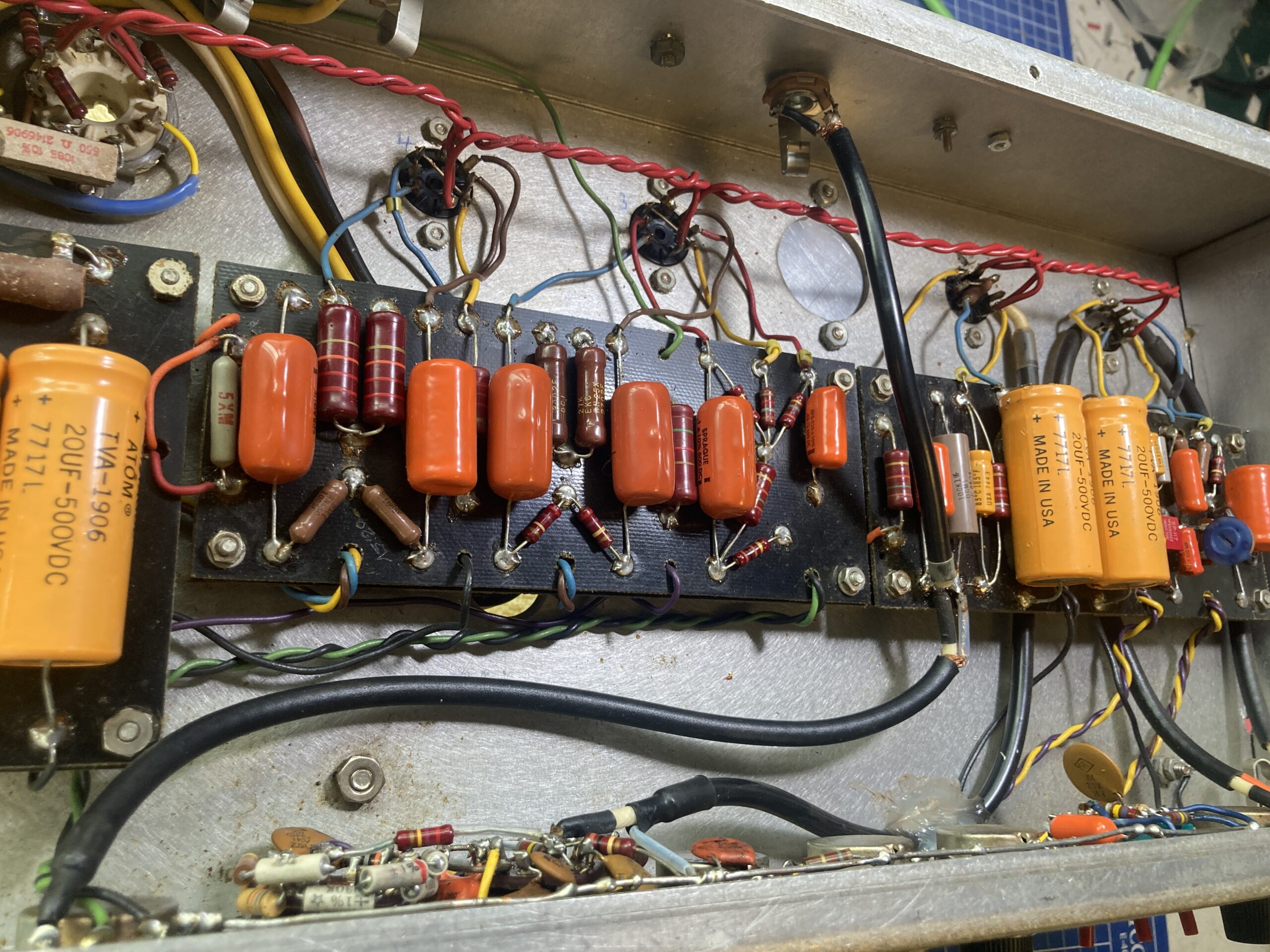
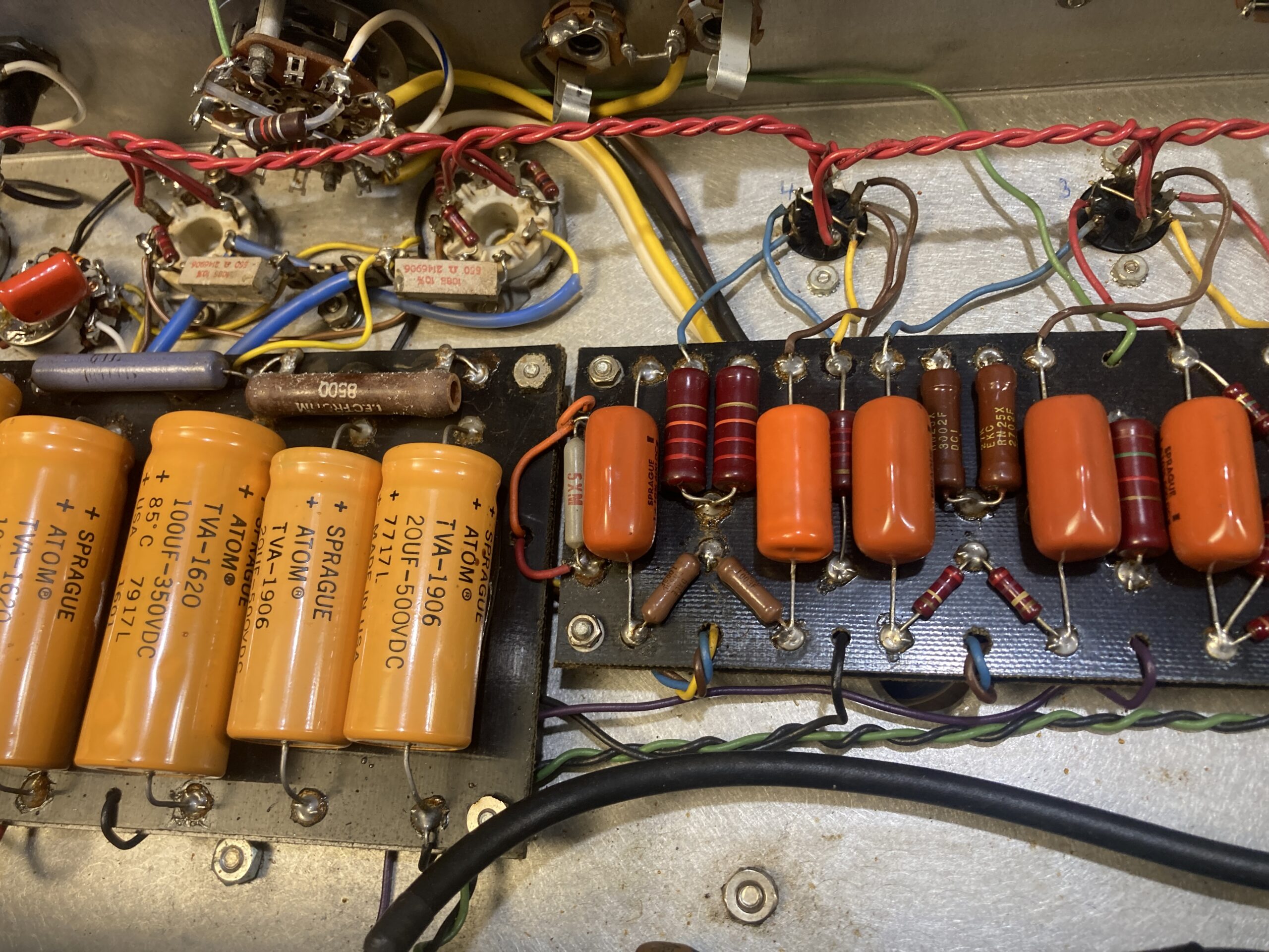
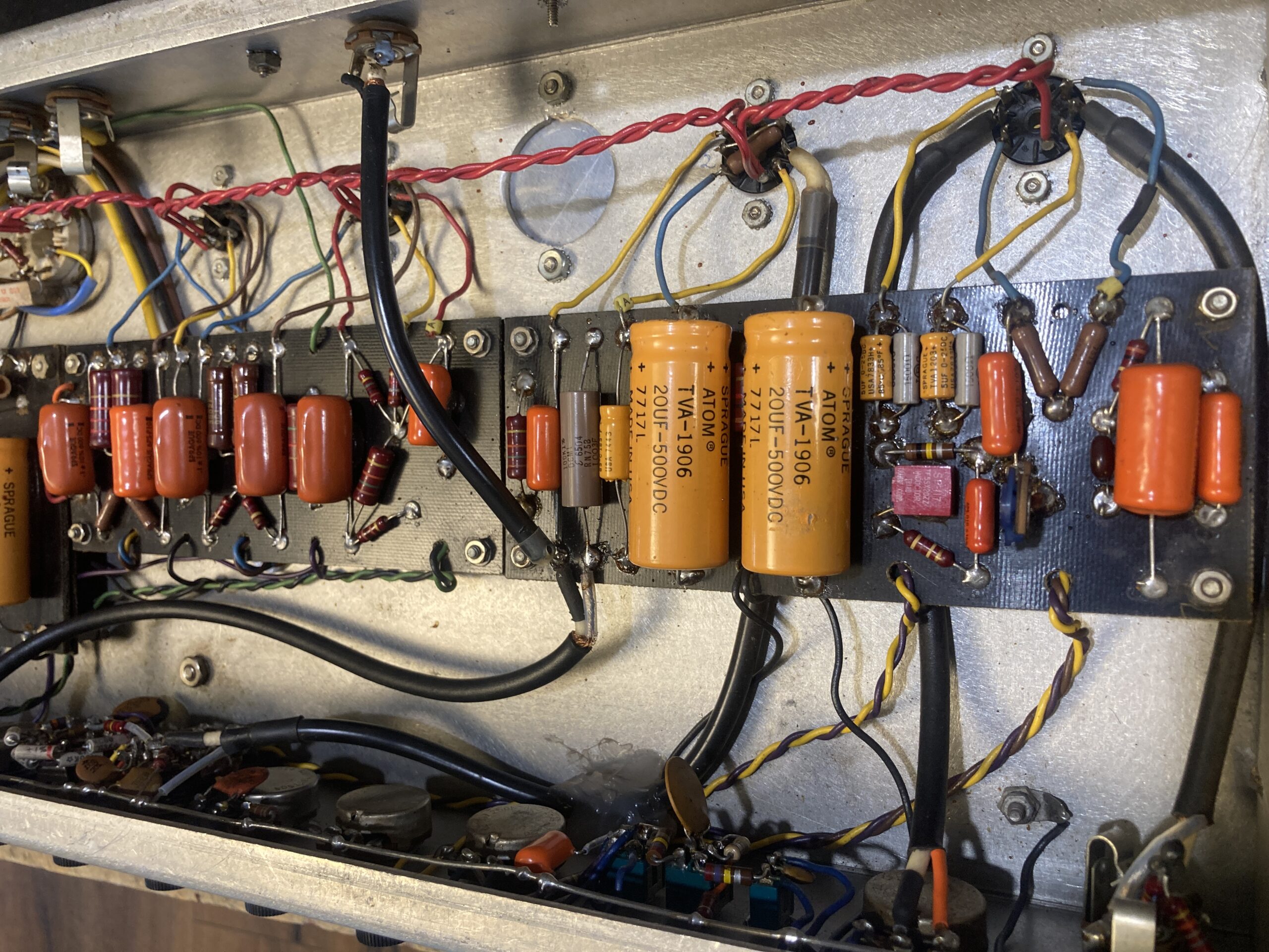
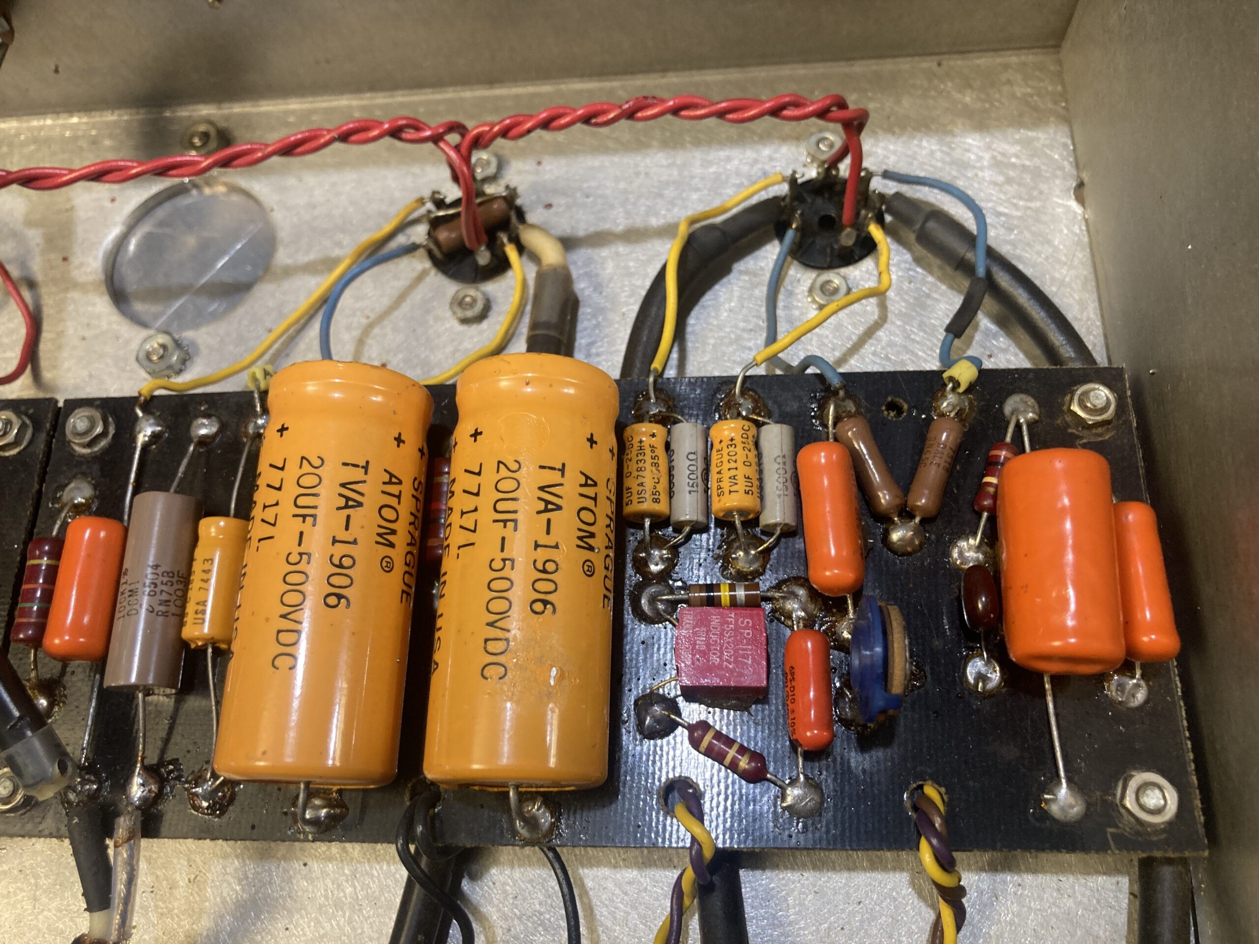
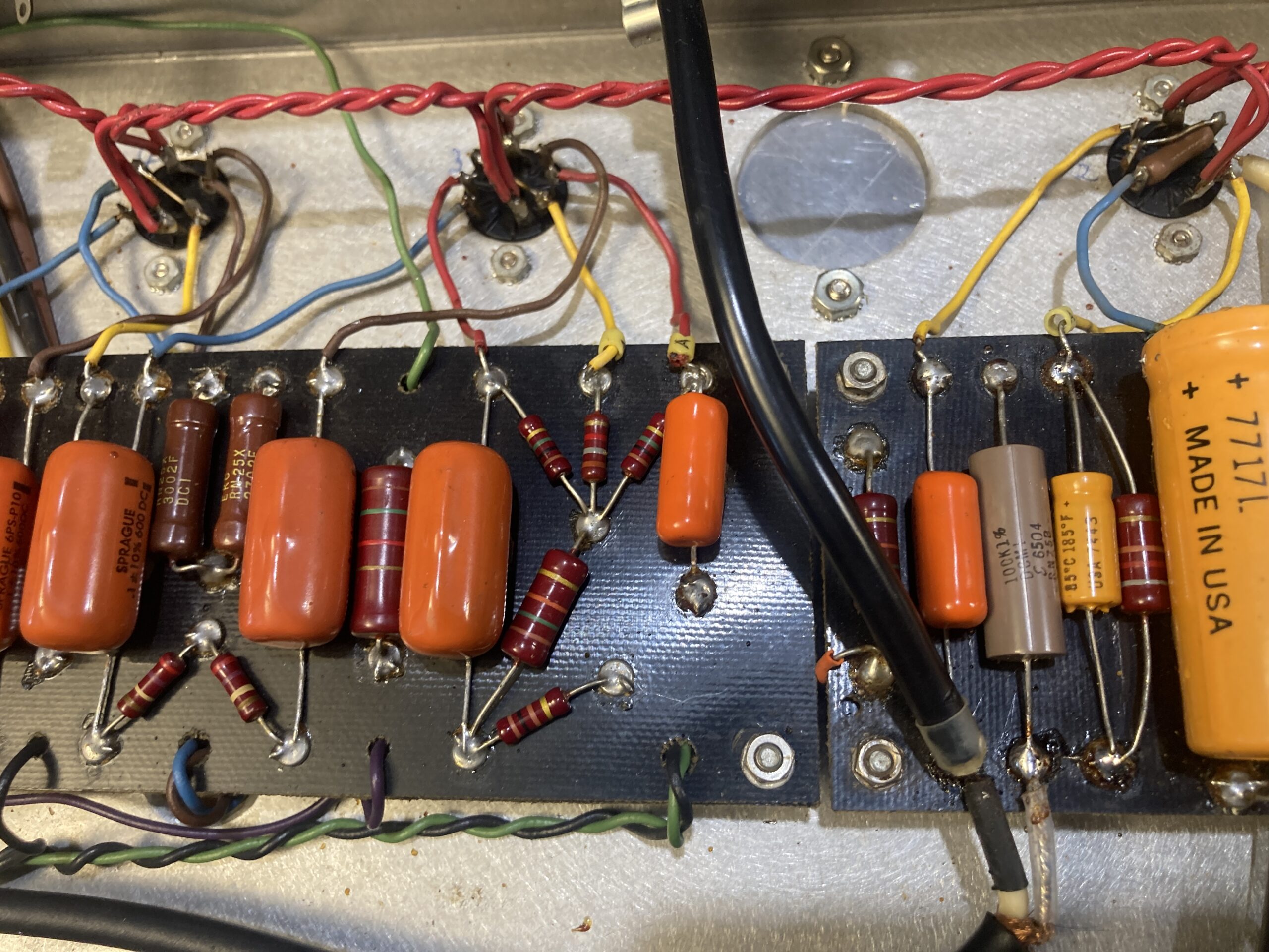
The large filter capacitors are labeled with codes ranging from 7717 to 7839—Week 17 of 1977 to Week 39 of 1978. This supports the idea that it was completed in 1978–79.

The Prelude to Dumbleland Special #011: Familiar Pattern, Unknown Values

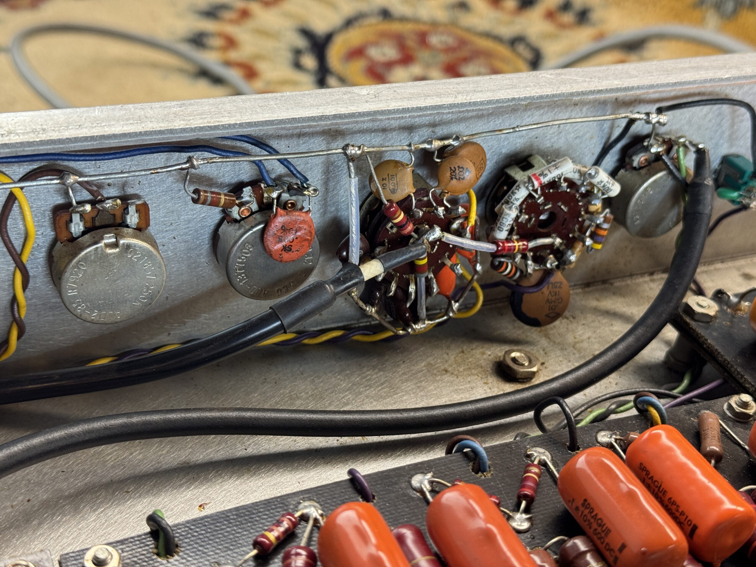
The input stage follows the classic Dumble design: Rock/Jazz switch, Deep, Bright—it’s all there, just as you’d expect. Things get interesting after the second triode: Here, Dumble has incorporated an additional tone control that resembles a Baxandall circuit. Labeled “Step” — separate controls for treble and bass.
This step circuit is a familiar feature of other Dumble amps. But with these component values? Extremely rarely documented.
This is followed by a classic cathode follower, and then the master volume: a 1-MΩ potentiometer that already passes 30% of the signal at the midpoint. Translation: This amp is already very loud at the 12 o’clock position. There is no provision for room occupancy here.

Phase Inverter and Power Amplifier
Phase inversion is handled by a 12AU7 in a long-tail pair circuit—reliable, proven, and unobtrusive. What’s particularly noteworthy is that behind it sits a 12BH7, serving as a dedicated driver stage for the power amplifier grids. The 12BH7 can deliver significantly more current than the standard 12AX7 or 12AT7 and ensures that the power tubes operate cleanly and at full drive. Dumble has gone the extra mile here, more so than most amp builders would.

The power tubes are 6550s—tubes that are more commonly found in hi-fi or bass amps than in guitar amps. And here’s the key point: Dumble doesn’t run them in ultra-linear mode here. Instead, the shielding grids are connected to the power supply via 550-Ω resistors. That may sound like a minor detail, but it fundamentally changes the character: less tight, less linear, but with more character, more compression—more amp.
Fixed bias, as you’d expect. The bias circuit is simple—it’s not rocket science.
The NFB tap is switched together with the output impedance. If you change the speaker connection, the negative feedback value also changes automatically. This isn’t just a gimmick, but a deliberate adjustment: Different impedances at the output transformer alter the turns ratio and thus the damping factor—Dumble compensates for this via the NFB value so that the amp sounds controlled under any load.
There’s an easier way to do this, but the master does it right!

Clues and Mysteries
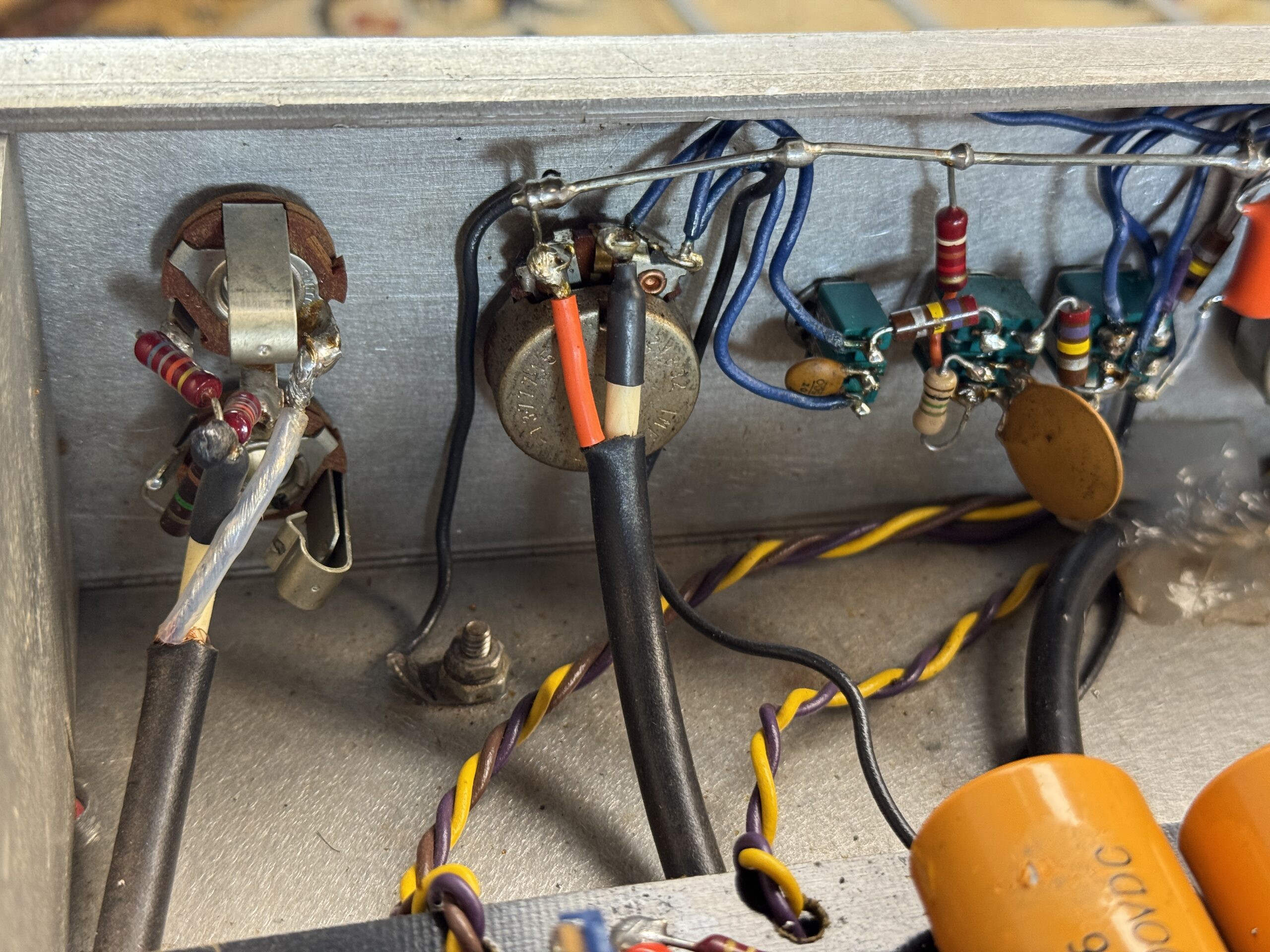
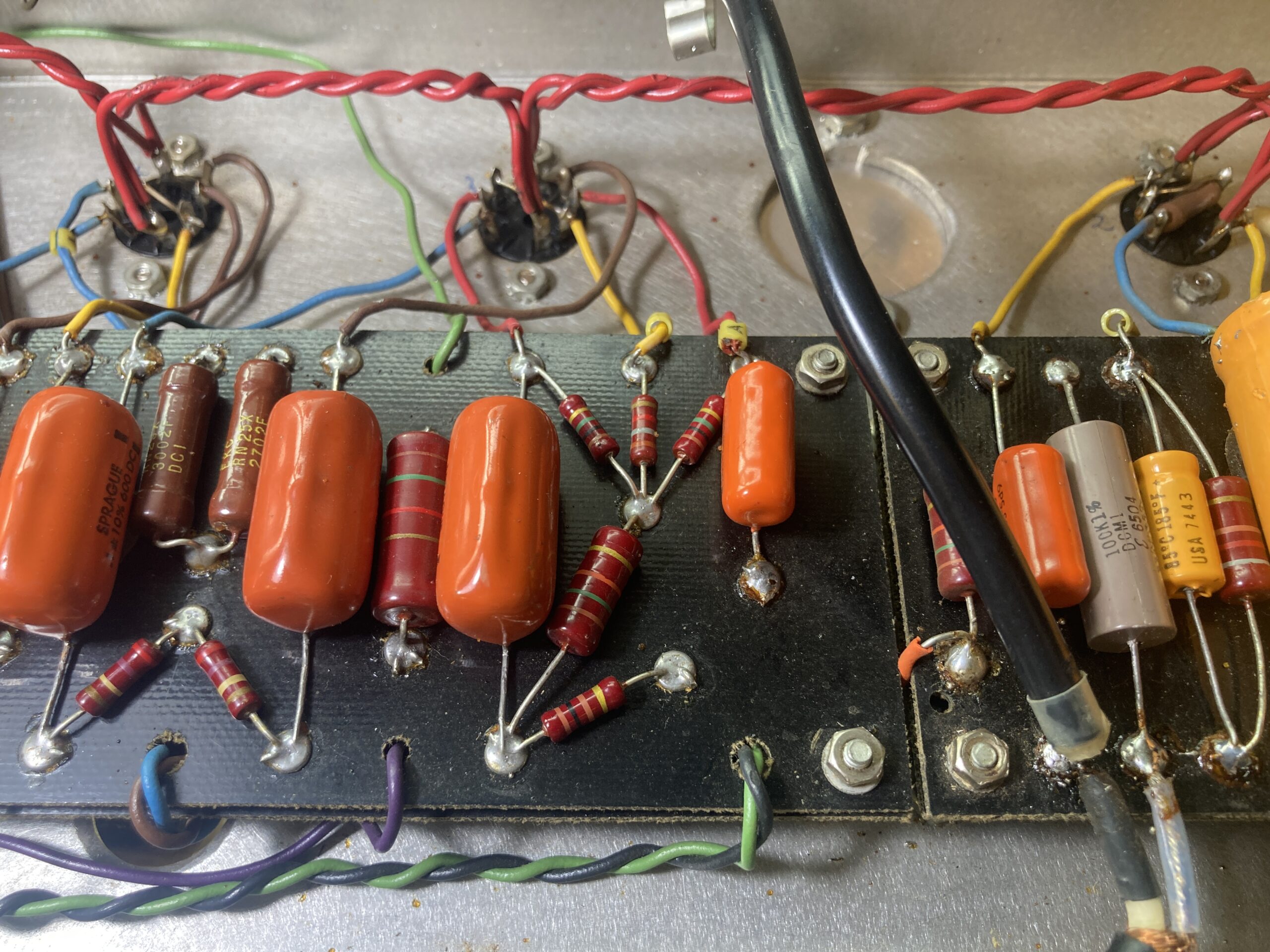
A hand-built Dumble is always an archaeological project as well. We noticed several peculiarities with #011:

Standby light:
Probably retrofitted—perhaps even by Dumble himself? These types of resistors are not normally found in the amplifier.

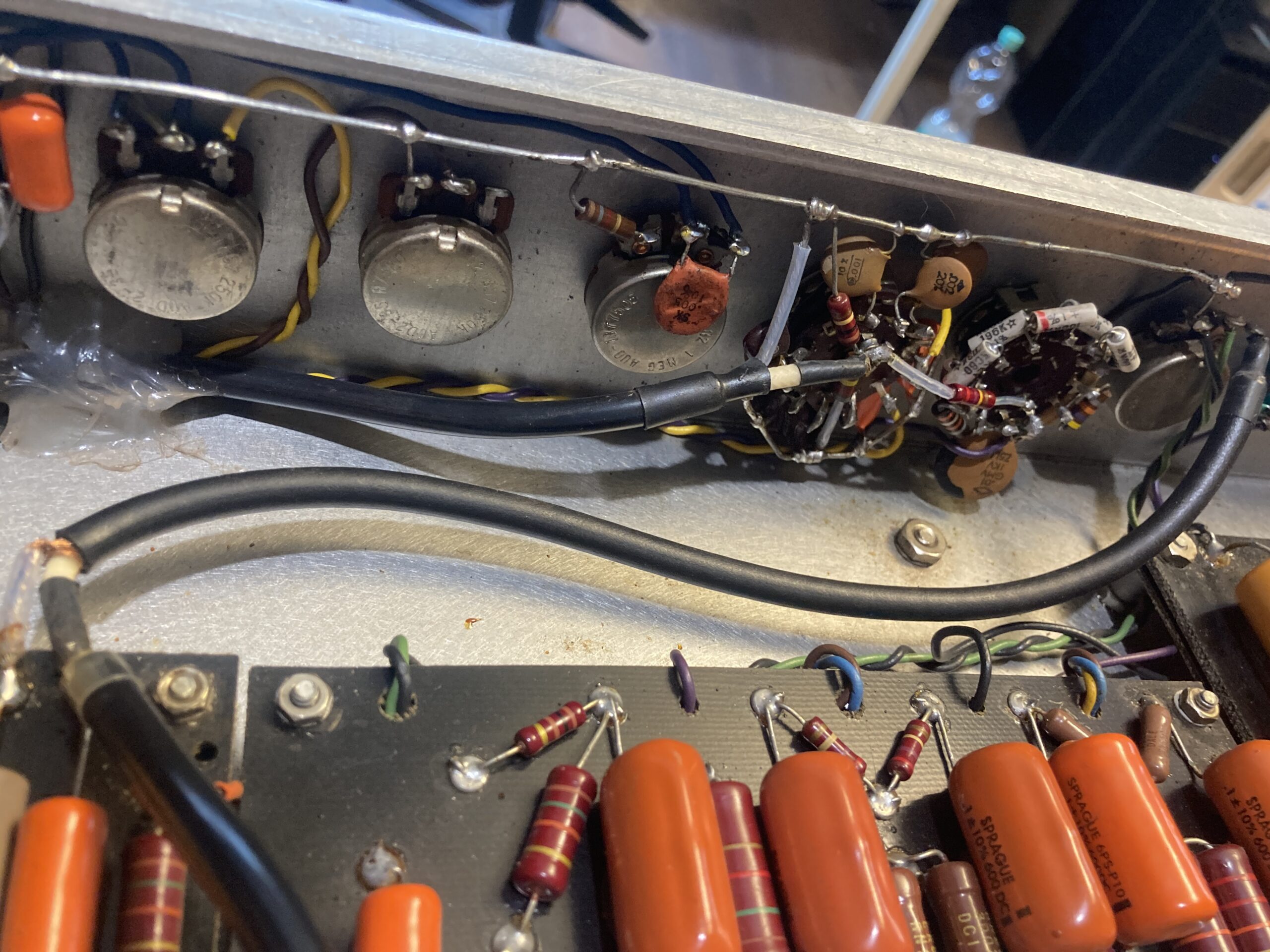
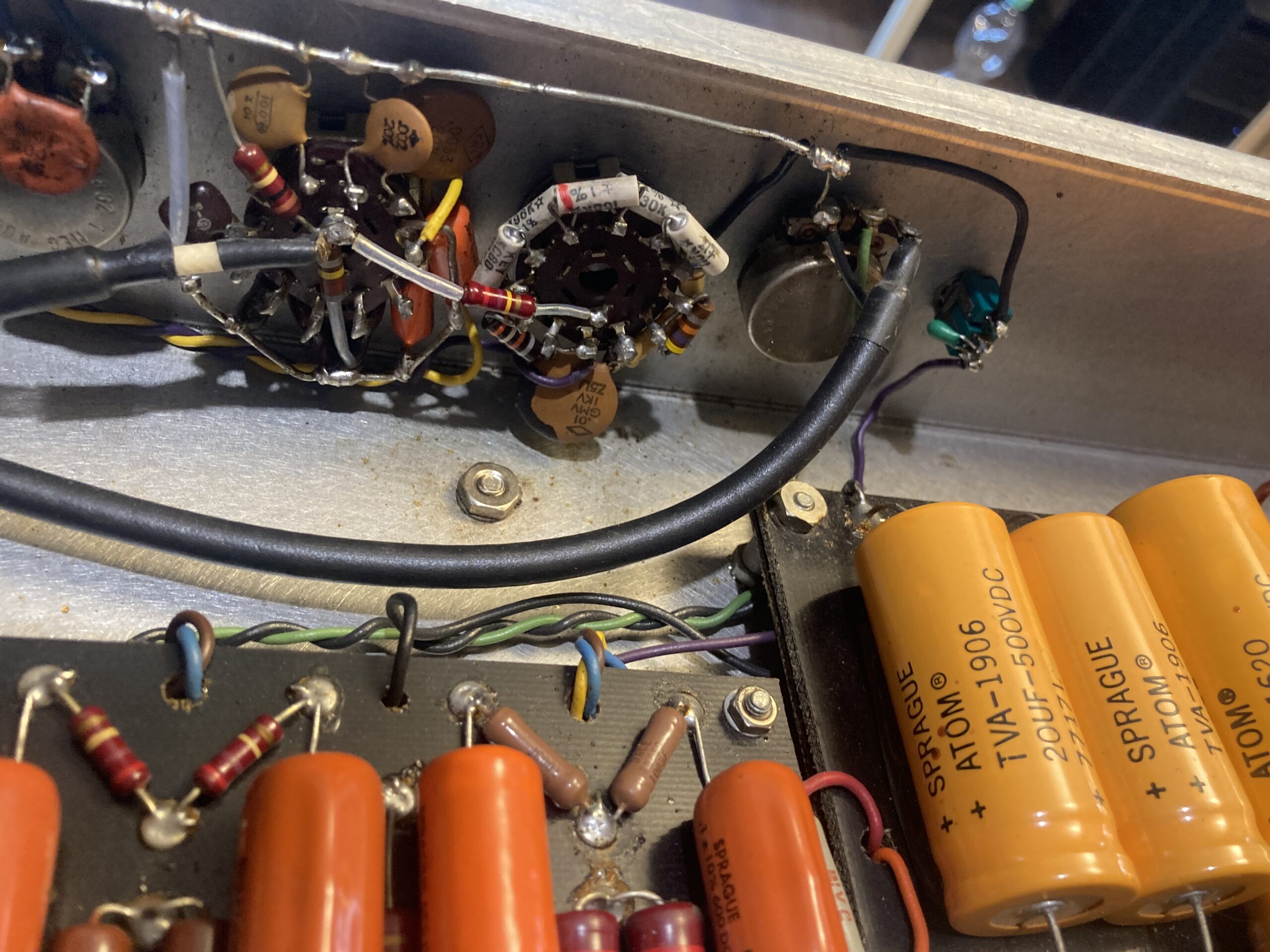
Hole in the chassis:
We can’t explain this hole either.

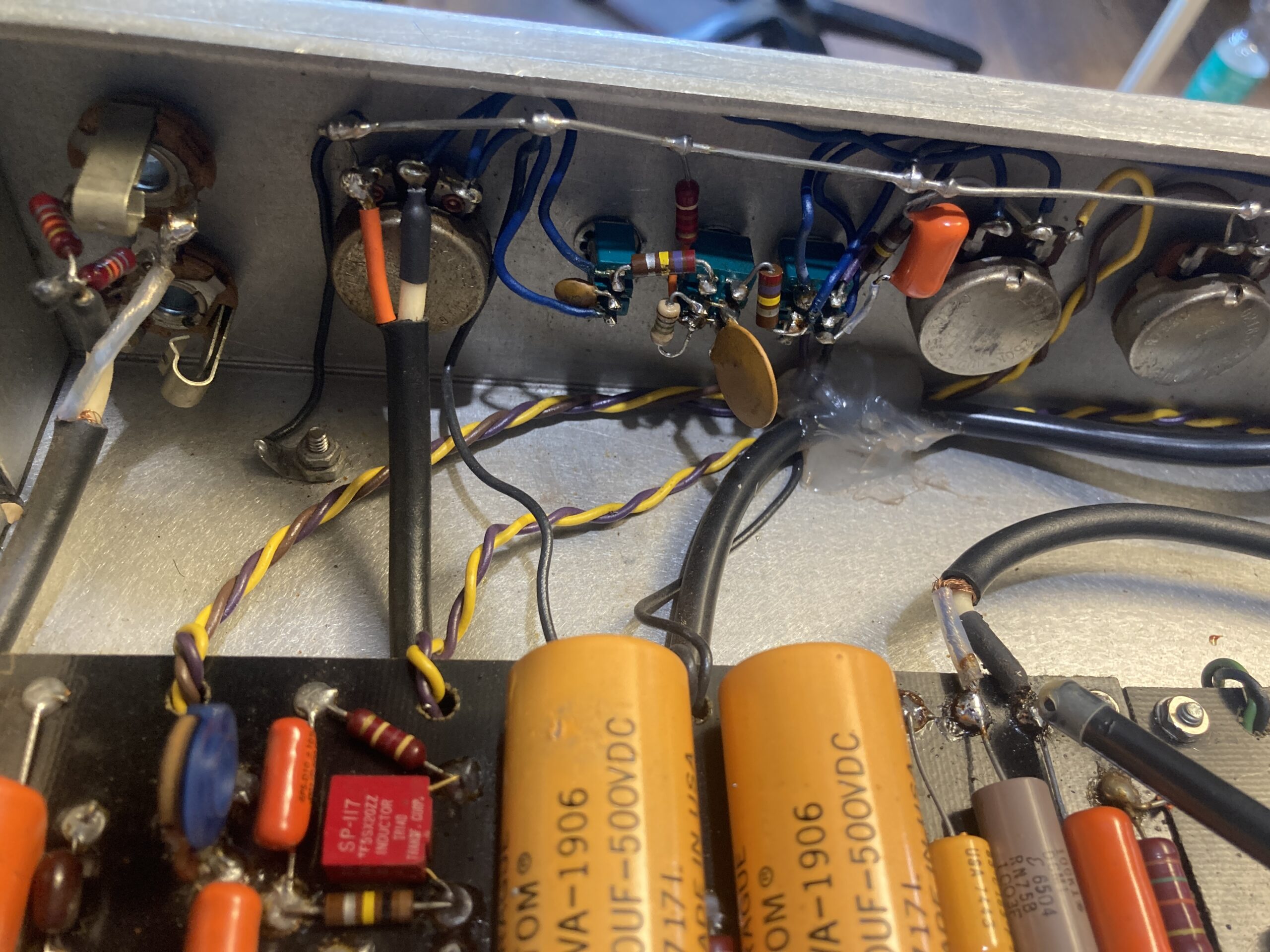
“A” rings on cables:
Function unknown. Production labeling? Sorting?
It can’t stand for “A-node,” because some wires are also cathode connections.

Holes in the back panel:
There is no explanation for why there are two holes in the back panel. Nor is it clear why two different types of screws or nuts were used to secure it.

Closed chassis hole:
Earlier Dumbleland models had a capacitor here, which was moved to the circuit board in model #011—the series has evolved over the course of production.

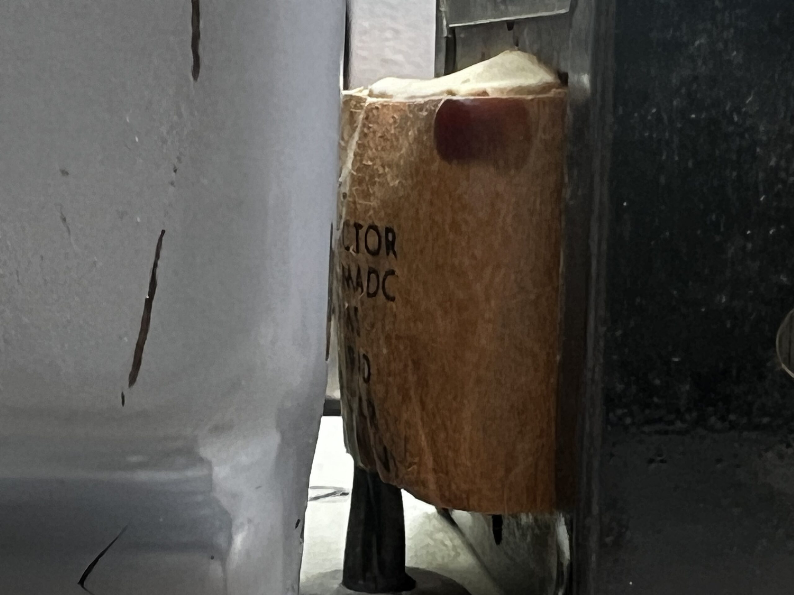
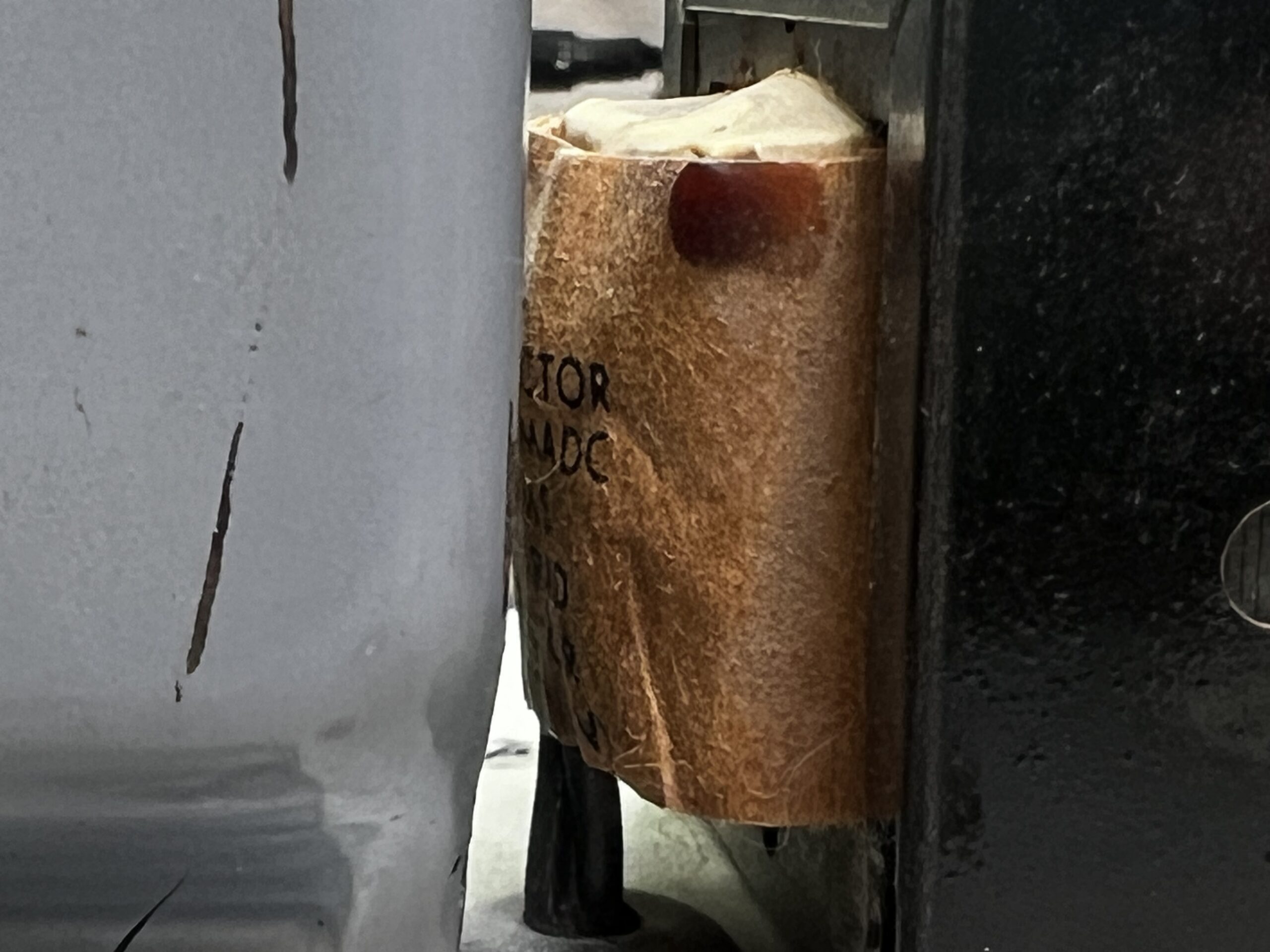
Handwritten inscription on a capacitor?: Unfortunately, it’s indecipherable—perhaps the manufacturer’s autograph? Otherwise, there is no signature on the chassis.


Fun Fact:
The NFB connection on the impedance selector switch was probably never actually soldered; if it was, it was done with very little solder. It has held up well over the years, though, because Mr. Dumble wrapped the wire ends around the terminals before soldering them. As it should be: Ensure mechanical stability before applying solder.
What Remains
The Dumbleland Special #011 isn’t an Overdrive Special or a Steel String Singer—it’s something earlier, rawer, and more experimental. The combination of choke-input filtering, a 6550 without ultralinear configuration, a triple-cascaded tone control, a 12BH7 driver, and switchable negative feedback reveals a designer who pushed the boundaries. Some of these ideas reappear in later Dumble designs, while others were discarded.
For circuit archaeologists, this amp is a treasure trove. For everyone else: one of the rarest models from one of the rarest series in guitar amplifier manufacturing.
And it’s for sale!